To precisely control a linear actuator‘s movement, calculating its position is key. This involves three crucial pieces of information: the actuator’s total travel distance (length), its starting point, and the desired final position. With these values in hand, a simple formula unlocks the secret: Position = (Final Position – Starting Position) / Length of Actuator.
In essence, calculating the position clarifies the exact distance the actuator needs to travel to reach its designated endpoint. Mastering this calculation empowers you to program precise movements, ensuring your project operates with optimal efficiency and achieves flawless results.
Demystifying Linear Actuator Position Calculations
In the realm of industrial automation, linear actuators play a pivotal role in transforming rotary motion into linear motion, powering a wide range of applications from simple opening and closing mechanisms to complex robotic systems. Understanding how to calculate linear actuator position is crucial for ensuring precise control and achieving desired outcomes in these applications.
The Basics
Before diving into the calculations, let’s establish the fundamental concepts that underpin linear actuator position determination. The position of a linear actuator refers to the distance its rod or shaft has extended from its fully retracted position. This distance is typically measured in millimeters (mm) or inches (in).
Dimensions
The dimensions, displayed on the left side of the calculator, represent the information you input to specify your particular application. You can modify these values to determine a suitable linear actuator with appropriate mounting positions.
Box Width
The box width, measured in inches, indicates the width of the space underneath your hatch. This value may influence the physical size of a suitable linear actuator depending on the mounting positions. Typically, it corresponds to the width of the lid itself, but in some cases, you may have more space beneath the lid than its width.
Box Height
The box height, measured in inches, represents the depth of the space underneath your hatch. This value is particularly crucial when space beneath the hatch is limited, such as with a tonneau cover on a pickup truck, as it will restrict the physical size of a suitable linear actuator. When there is ample space underneath the lid, like with a trapdoor to a cellar, the box height becomes less significant.
Lid Weight
The lid weight, measured in pounds, represents the weight of the lid you intend to open or the size of the load you plan to rotate. Naturally, this value will significantly impact the selection of an appropriate linear actuator for your application.
Max Angle
The max angle, ranging from 0 degrees (closed) to 90 degrees, indicates the maximum angle at which your lid will open. Once again, this value will have a substantial influence on the potential linear actuators available for your application.
Lid Mount Position
The lid mount position, measured in inches, represents the location where your linear actuator will be attached to the lid. This value can vary from 0 inches to the box width or the end of the hatch. If you have flexibility in mounting the linear actuator to the lid, you can adjust this value to find results that best suit your application. However, in certain applications, the position where you can mount the linear actuator to the lid may be restricted.
Actuator Type
The actuator type refers to the type of actuator you intend to use. Your choice of actuator type may depend on your application or desired features, such as feedback options. You can explore the various types of linear actuators available in our store to determine which one is best for you. If you’re not particular about the type, you can experiment with different actuator types in the calculator to identify the one that best meets your needs.
Choose Actuator
Once you select a specific actuator type, you will then choose an actuator of that type with a particular stroke length. Since you may be unsure of the required stroke length, you can easily try out different lengths to determine if that particular actuator will fit your needs.
Number of Actuators
The number of actuators indicates the quantity of actuators involved in your application. While you can select either 1 or 2, the calculator will default to recommending using 2 actuators (one mounted on either side of the hatch) as it provides greater stability. It is never advisable to push a hatch open from just one side. We do offer the option to change to 1, but only do this if you are mounting the actuator in the center of the hatch.
Factors Influencing Linear Actuator Position
Several factors influence the position of a linear actuator, including:
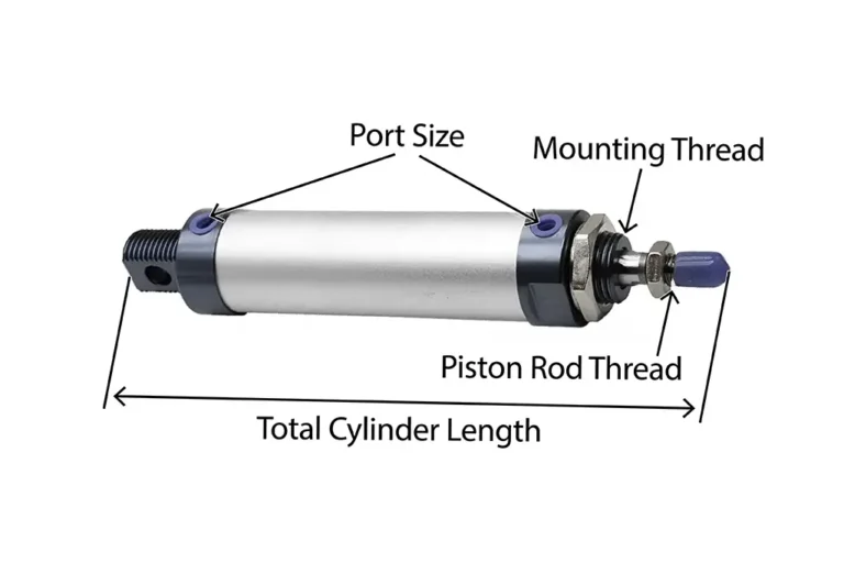
- Stroke: The stroke of a linear actuator represents the maximum distance its rod or shaft can extend.
- Extension Rate: The extension rate, also known as the speed, determines how quickly the actuator extends its rod or shaft.
- Retraction Rate: The retraction rate, also known as the speed, determines how quickly the actuator retracts its rod or shaft.
- Control Mechanism: The control mechanism dictates the method by which the actuator is commanded to extend or retract. Common control mechanisms include electric signals, pneumatic pressure, or hydraulic pressure.
Calculating Linear Actuator Position
Now that we’ve grasped the fundamental concepts, let’s delve into the practical aspect of calculating linear actuator position. The primary formula for calculating linear actuator position is:
Position = Stroke × Extension Percentage
Where:
- Position: The distance the actuator’s rod or shaft has extended from its fully retracted position, typically measured in millimeters (mm) or inches (in).
- Stroke: The maximum distance the actuator’s rod or shaft can extend, typically measured in millimeters (mm) or inches (in).
- Extension Percentage: The percentage of the stroke that the actuator has extended. This value is typically expressed as a decimal between 0 and 1, where 0 represents fully retracted and 1 represents fully extended.
Example Calculation:
Consider a linear actuator with a stroke of 100 mm and an extension percentage of 50%. Applying the formula, we get:
Position = 100 mm × 0.5 = 50 mm
Therefore, the actuator’s rod or shaft has extended 50 mm from its fully retracted position.
Real-World Applications: Bringing Calculations to Life
Linear actuator position calculations play a crucial role in various real-world applications, such as:
- Precision Positioning: In robotic systems, precise positioning of grippers and manipulators relies on accurate calculations of linear actuator position.
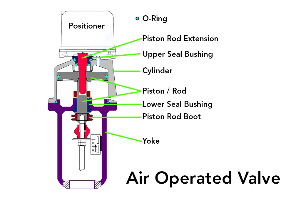
- Automated Machinery: Linear actuators are often employed in automated machinery for tasks like opening and closing valves, moving components, or adjusting positions. Precise positioning calculations ensure accurate and repeatable operation.
- Motion Control Systems: Linear actuator position calculations are essential in motion control systems, where precise control of movement is critical for achieving desired outcomes.
Unveiling the Power of Precision
Understanding how to calculate linear actuator position empowers engineers and technicians to make informed decisions regarding the selection, control, and optimization of these versatile components. By mastering these calculations, you can harness the power of linear actuators to achieve precise positioning, enhance automation processes, and optimize motion control systems. Embark on this journey of precision and unlock the full potential of linear actuators in your industrial endeavors!
To get a full picture on how to install a linear actuator, read this blog.