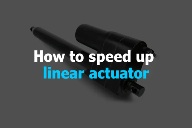
If you’re wondering how to make a linear actuator faster, there are several proven ways to speed up your fast linear actuator safely. You can raise the voltage with proper control, change the gear ratio, get a higher lead screw pitch, or use a motor controller to fine-tune speed. Techniques like PWM control using an Arduino and switching to a high speed actuators type, such as hydraulic or pneumatic, can also help. Regular maintenance, reducing friction, and optimizing the mechanical load can further improve the performance of your fast actuators linear.
What is fast linear actuator?
A high speed linear actuator 12v is like a super-fast mover in a straight line. Designed to zip back and forth quickly, faster than standard units, these actuators use powerful motors and lightweight materials to move fast while still being accurate and reliable. Fast linear actuators are ideal for applications like robotics and automated machinery where speed and precision are essential.
Effective Ways to Speed Up These Device
To speed up linear actuator, you can adjust several factors. Increase the voltage to the motor for more power, modify the gear ratio to increase speed, and consider upgrading to a stronger motor. Reducing friction by lubricating moving parts and simplifying the actuator’s design can also help.
Characteristics of High-Speed Linear Actuator
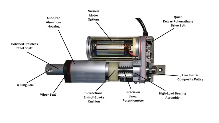
High-speed linear actuators exemplify swift, precise motion with rapid acceleration and deceleration rates. Compact and lightweight, they boast efficient energy usage, integrating feedback systems for enhanced control.
Their durable construction, low inertia, and versatile applications make them ideal for dynamic industrial settings, ensuring reliability, longevity, and ease of integration into diverse automation systems.
7 Ways to Speed Up Linear Actuator
Here are 7 proven strategies to make your fast linear actuator operate at optimal speed:
1. Adjusting Voltage
Increasing the voltage in a linear actuator can be a dangerous and potentially damaging process if done incorrectly. Before attempting any adjustments, it’s crucial to understand the specific model of your actuator and its capabilities. Improper voltage can lead to overheating, malfunctions, and even electrical shock.
Here are some safe and recommended ways to increase the speed of a linear actuator:
Pulse Width Modulation (PWM): Many linear actuators use PWM for speed control. Increasing the duty cycle (on-time) of the PWM signal can provide more power and speed within the actuator’s safe operating range.
Control signal adjustment: Some linear actuators accept analog or digital control signals. Adjusting the signal within the specified range can increase the speed.
Consult the manufacturer’s instructions: The manual or data sheet for your specific actuator should provide detailed information on its voltage range, safe operating limits, and recommended control methods. Never exceed the manufacturer’s recommended voltage for your specific model.
Consider alternative solutions: Using a larger or more powerful actuator model may be a safer option than exceeding the voltage limits of your existing one. Gearing can be used to increase the force output of an existing actuator at the cost of reduced speed.
Additional Considerations: Wear appropriate personal protective equipment and follow the manufacturer’s safety guidelines. Use specialized tools and techniques if required for precise gear adjustments. If you’re unsure about the process, consult with a qualified technician or contact the manufacturer for assistance.
2. Adjust Gear Ratio
While adjusting the gear ratio within a single linear actuator is typically not feasible, here are the common approaches to achieve the desired speed-to-force characteristics for your application:
Select the Right Actuator at the Outset: Manufacturers often offer linear actuators with varying gear ratios, each designed to provide specific speed and force combinations. Carefully review the available options to choose the model that best aligns with your project’s requirements.
Utilize External Gearing: If necessary, you can install additional external gears to create a custom gear ratio that suits your needs. This approach involves adding gears between the actuator’s output shaft and the driven load.
Employ a Motor Controller: For fine-tuning speed control without altering the gear ratio, consider using a motor controller or a linear actuator control board. These devices allow you to adjust the actuator’s speed, end limits, and sensitivity through electronic means.
Additional Considerations: Ensure your application can handle the reduced force output before adjusting the gear ratio. Always consult the actuator’s user manual or contact the manufacturer for specific instructions and recommendations regarding gear ratio adjustments or modifications.
3. Lead Screw Pitch
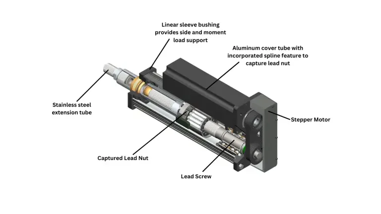
The lead screw is a crucial component that converts rotary motion into linear motion. Opting for a lead screw with a higher pitch (distance traveled per screw revolution) results in faster linear movement. Here are key approaches to achieving the desired linear motion speed with a lead screw pitch:
Select the Appropriate Actuator: Manufacturers offer linear actuators with varying lead screw pitches. Each influences speed and travel distance per motor revolution. Choose an actuator with a pitch that aligns with your speed and distance requirements.
Utilize External Gearing: Employ external gears to modify the effective lead screw pitch. Install a gear train between the actuator’s motor and lead screw to alter the rotational speed and linear travel distance per motor revolution.
Control Speed Electronically: For fine-tuning speed without altering the lead screw pitch, use a motor controller or linear actuator control board. These devices adjust motor speed, end limits, and sensitivity, impacting linear motion without physically adjusting the lead screw.
Additional Considerations: Lead screw pitch impacts speed and resolution. A finer pitch yields slower speed but higher resolution (smaller incremental movements), while a coarser pitch offers faster speed but lower resolution.
4. Use Motor Controller or LAC Board
These devices offer fine-grained control over motor speed, allowing for precise adjustments. Check compatibility with your actuator model before purchasing a controller or board:
Compatibility Check: Verify that the controller is compatible with your actuator model and voltage requirements. Consult the controller’s specifications and the actuator’s manual for confirmation.
Electrical Connections: Connect the power supply to the controller, ensuring proper voltage and polarity. The linear actuator’s motor wires to the corresponding terminals on the controller. If using external control signals (e.g., switches, sensors), wire them to the appropriate controller inputs.
Configuration (if applicable): Some controllers may require programming or setting specific parameters.
Additional Considerations: Disconnect the power before making any wiring changes. Ensure adequate airflow and cooling for the controller, especially at higher loads. Some controllers offer feedback signals for monitoring actuator position and status. Refer to the controller’s troubleshooting guide if any issues arise.
5. Arduino or Microcontroller
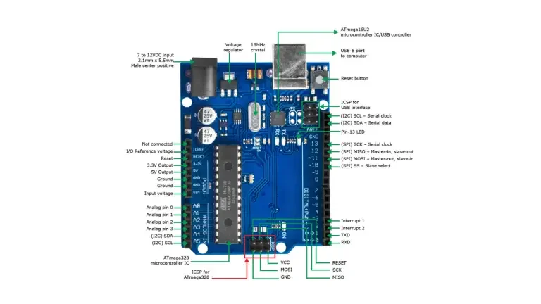
To speed up a linear actuator using Arduino or a microcontroller, you can leverage the Pulse Width Modulation (PWM) capabilities to control the power supplied to the actuator’s motor. Here’s a step-by-step guide:
Hardware Setup
Select a Suitable Actuator: Ensure that your linear actuator is compatible with PWM control and can handle the increased speed.
Connect the Actuator to the Microcontroller: Connect the power, ground, and control (signal) wires of the linear actuator to the corresponding pins on the microcontroller. Refer to the actuator and microcontroller datasheets for pin configurations.
Power Supply Considerations: Make sure that the power supply to the actuator and the microcontroller meets the voltage and current requirements of both components.
Software Programming
Write a Basic Program: Use the Arduino IDE or your preferred microcontroller programming environment to write a basic program. Include the necessary libraries and define the pins for actuator control.
Initialize PWM Output: Configure one of the PWM-capable pins on the microcontroller for controlling the actuator speed. In Arduino, this is often achieved using the ‘analogWrite()’ function.
int actuatorPin = 9; // Example PWM pin
void setup() {
pinMode(actuatorPin, OUTPUT) ;
}
Adjust PWM Duty Cycle: Use the ’analogWrite()’ function to set the PWM duty cycle, which controls the average power supplied to the actuator. A higher duty cycle corresponds to increased speed.
void loop() {
analogWrite(actuatorPin, 200); // Example duty cycle value (0 – 255)
}
Gradual Speed Adjustments: Implement logic in your code to gradually adjust the duty cycle. This can be achieved using loops, conditional statements, or external inputs (potentiometer, sensors) for dynamic control.
void loop() {
for (int i = 0; i <= 255; i++) {
analogWrite (actuatorPin, i) ;
delay(10) ; // Adjust delay for smooth changes }
}
Safety Measures: Implement safety features, such as limit switches or emergency stop functionality, to ensure the linear actuator operates within safe limits.
Testing and Calibration: Upload the program to the microcontroller and test the linear actuator’s speed response. Calibrate the program as needed for your specific application.
Fine-Tuning: Fine-tune the speed control logic in your code based on real-world performance and requirements.By adjusting the PWM duty cycle through programming, you can effectively control and increase the speed of a linear actuator using an Arduino or microcontroller.
6. Select a Different Actuator Type
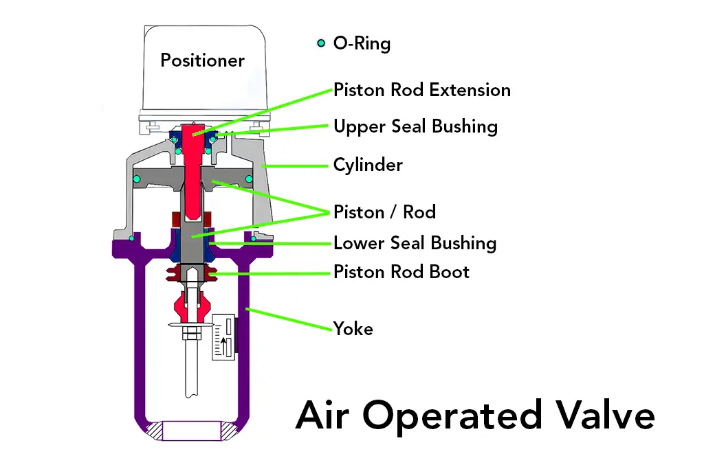
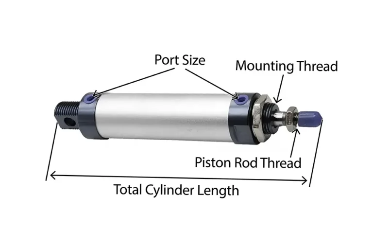
Hydraulic and pneumatic linear actuators are often inherently faster than electric actuators, reaching higher speeds with less effort.
Consider their unique requirements for fluid or air supply and potential for increased complexity.
7. Optimize Mechanical Efficiency
Minimize friction in the actuator’s components through proper lubrication and maintenance to enhance speed and efficiency. Decrease the load on the actuator, if possible, to improve its speed capabilities.
Speed Up Your Linear Actuator with Expert Solutions from Maxim Systems
Without expert insight, speeding up a high speed linear actuator 12v can lead to complications or even damage. MaximSystems provides custom strategies to enhance actuator performance across all applications.
Whether you’re adjusting gear ratios or implementing microcontroller-based control, we offer precise, tailored solutions to help you achieve optimal speed and performance with your fast linear actuator. Trust Maxim Systems to deliver high-end, reliable results with your high speed actuators setup.
