How to Clean Purge Solenoid Valve? (The Complete Guide)

If you’re having trouble starting your car, or find it shaking unnaturally when in an idle state, chances are, your car has a clogged purge solenoid valve. It’s easy to clean a dirty purge solenoid valve though. Here’s a simple guide on how to clean purge solenoid valve. Before we get started, let’s understand what a purge solenoid valve is. What is a Purge Solenoid Valve? Your car’s evaporative emission control system, also known as the EVAP system, has a crucial part called the Purge Solenoid Valve. This valve acts like a gatekeeper, controlling the flow of fuel vapors from a charcoal canister back into the engine. Signs of a Bad Purge Solenoid Valve A faulty purge solenoid valve can cause several problems in your car. Tools Required to Clean Purge Solenoid Valve Here’s a list of tools required how to clean a Purge Solenoid Valve: How To Clean Purge Solenoid Valve Quickly: (The step-by-step guide) To get started, at first we ought to learn how to detach a Purge Solenoid Valve. Just follow these simple steps. Step-1: Turn off the engine and let it cool down Since the purge valve is located under the hood, it’s important for the engine to be cool before you start working. If you’ve just driven the car, wait at least 10 minutes to allow the engine to cool down sufficiently. Step-2: Wear Gloves and Safety Glasses Protect your eyes, hands and skin from possible dirt and debris splatters onset by the cleaning process. Step-3: Pop The Hood Open & Locate The Solenoid Valve Near the driver’s side, on the right side of the engine, look for a silver, round component called the throttle body. The Solenoid Valve is usually positioned underneath the throttle body. The Solenoid Valve is usually a small, black component that has two rubber hoses connected to it (one hose connecting to a black canister and other connecting to a larger metal pipe). Step-4: Detach The Solenoid Valve Once you disconnect the negative battery terminal, detach the purge solenoid valve using a wrench/socket set. Make sure you remove the electrical connector and vacuum lines properly. Step-5: Cleanse The Solenoid Valve Spray throttle/carburetor cleaner onto the Solenoid Valve, making sure that the cleaning agent reaches all internal parts of the valve. Let the cleaning agent sit for a few minutes, so any dirt or debris found inside dissolves properly. You can now gently shake the valve to remove any stubborn particles. Step-6: Rub The Valve Clean Use a rag or a piece of clean cloth to rub the internal and external surface area of the Purge Solenoid Valve thoroughly, making sure to rub off any remaining dirt or debris. Finally, wipe it completely dry before reconnecting the valve. Step-7: Re-install The Valve Using the socket set or wrench, reconnect the now dry valve to the hoses and the electrical connection. Step-8: Reconnect The Battery After you’ve reinstalled the Purge Solenoid Valve to the Vacuum lines & Electrical connector, make sure you’ve tightened the nuts and bolts properly. Once done, reconnect the negative battery terminal. When to Replace Your Purge Valve Solenoid? Even after cleaning your purge valve solenoid, there are some signs that it might be time for a replacement: Stubborn Check Engine Light: If the “check engine” light stays on after cleaning, it suggests the valve itself might be faulty and needs to be swapped entirely. Performance Problems Persist: Continuing issues like rough idling, starting difficulties, or poor gas mileage after cleaning indicate the valve might need replacing. Emissions Test Failure: A failed emissions test with the purge valve suspected as the culprit suggests replacement is necessary. Physical Damage is Evident: Cracks, breaks, or excessive wear on the purge valve mean cleaning won’t fix the problem. It’s time for a new one. Frequent Cleaning Needs: If you find yourself needing to clean the valve constantly for it to function, it’s probably failing and needs to be replaced. Why Cleaning Your Purge Solenoid Valve is Important? Keeping your purge solenoid valve clean offers several benefits for your car: Smoother Running: A clean valve helps prevent problems like rough idling, trouble starting, and poor gas mileage. Your car will simply run better! Cleaner Emissions: The purge valve helps control how much pollution your car releases. Regular cleaning makes sure it’s working properly for a cleaner environment. Happy Fuel System: A clean purge valve is part of keeping your entire fuel system healthy, potentially saving you money on repairs down the road. Avoiding Check Engine Worries: A malfunctioning purge valve can trigger the dreaded check engine light. Cleaning it regularly helps prevent this unnecessary stress. Saving on Gas: A clean valve allows your engine to reuse fuel vapors instead of wasting them, improving your car’s fuel efficiency. Longer Valve Life: Regular cleaning can help your purge valve solenoid last longer, saving you the cost of replacing it sooner than needed. Conclusion The purge solenoid valve plays a vital role in your car’s performance and environmental impact. While cleaning it might seem like a small task, it can yield significant benefits. By keeping your purge solenoid valve clean, you’re contributing to a smoother running car, better fuel economy, and a cleaner environment. So, take some time for this simple maintenance task and keep your car happy for miles to come!
What is Solenoid Valve & How it Work (A Step-By-Step Guide)

Solenoid valves are remote-controlled gatekeepers for fluids. They use an electromagnet, called a solenoid, to manipulate a metal plunger. When electricity flows through the coil, it magnetizes it, attracting the plunger. This movement opens or closes internal passages in the valve body, controlling the flow of liquids or gases. With a spring pushing the plunger in the opposite direction, solenoid valves come in two types: normally open (spring keeps it open until activated) and normally closed (spring keeps it shut until activated). These versatile valves are used in everything from car engines to irrigation systems. What is a solenoid valve? A solenoid valve is a type of electromechanical device used to control the flow of fluids such as air, water, gas, steam, or other liquids. It consists of a coil of wire (solenoid) wound around a metal core, which generates a magnetic field when an electric current passes through it. This magnetic field causes a plunger or armature to move within the valve body, either opening or closing a passage for fluid flow. This guide provides comprehensive insight into solenoid valves, detailing their operational principles and offering clear guidelines for understanding their functionality. How does a solenoid valve work? A solenoid valve operates by utilizing an electromagnetic mechanism to regulate the flow of fluid through a passage. It comprises essential components such as a solenoid coil, plunger, valve body, ports, and a valve seat. When an electrical current passes through the solenoid coil, it generates a magnetic field that moves the plunger. This movement either opens or closes the valve, controlling the flow of fluid. Depending on its configuration (normally closed or normally open), the valve either allows fluid to flow or blocks it. How a solenoid valve actually works using its components. Let’s take a normally closed (NC) solenoid valve as an example: When there’s no electrical current, the coil isn’t energized. The spring takes charge, pushing the plunger down. This action forces the seal on the plunger to block the space in the valve body, essentially closing the gate and stopping any fluid flow. When electricity is applied to the coil, it becomes a mini magnet. This magnetic field pulls the plunger upwards against the spring’s force. As the plunger rises, it lifts the seal away from the orifice. This creates a clear pathway for the fluid to flow through the valve, opening the gate. Once the electrical signal ceases, the magnetic field disappears. The spring regains control, pushing the plunger back down. This closes the seal on the space once again, stopping the flow of fluid. By using electricity to control fluid flow electronically, it offers a simple and efficient solution for various applications. Their compact size, reliability, and versatility make them a valuable component in modern technology. The Working Principles Of Solenoid Valve Solenoid valves have two main parts, the solenoid and the valve itself. The valve has openings, while the solenoid contains a coil, sleeve assembly, and plunger. When you send electricity through the coil, it creates a magnetic field. This field moves the plunger up or down, which opens or closes the valve’s openings. This action controls the flow of gas or liquid, like turning a faucet on or off. Advantages & Disadvantages Of Solenoid Valve Solenoid valves are great because they serve multiple purposes in many industries. They’re good for handling liquids or gases, and they are quite efficient because they don’t need a lot of wiring or money to set up. Advantages Disadvantages What Types of Valves Are Used in Solenoid? There are 3 types of valves that offer versatility and flexibility in various applications, allowing for precise control of fluid flow in different systems. Two-way Solenoid Two-way solenoid valves are commonly used for on/off control. These valves have two ports. One port is for allowing the fluid to flow in one direction when the valve is energized, and another port is for blocking flow when de-energized. Three-way Solenoid Valve Two-way solenoid valves are commonly used for on/off control. These valves have two ports. One port is for allowing the fluid to flow in one direction when the valve is energized, and another port is for blocking flow when de-energized. Three-way Solenoid Valve Four-way solenoid valves are a type of solenoid valve with four ports: two inlet ports and two outlet ports. They are commonly used in pneumatic and hydraulic systems to control the flow of pressurized air or fluid and to switch between different circuits or actuate double-acting cylinders. Different Types Of Solenoid Valve There are 3 types of Solenoid Valves Normally closed Solenoid Valve A Normally Closed (NC) Solenoid Valve is a type of valve that remains closed in its default state, without any electrical power applied to the solenoid. When an electrical current is applied to the solenoid, it generates a magnetic field that lifts the valve’s plunger, allowing fluid to flow through the valve. Once the electrical current is removed, the solenoid de-energizes, and the valve returns to its closed position, stopping the flow of fluid. Normally open Solenoid Valve A Normally Open (NO) Solenoid Valve is a type of valve that remains open in its default state, without any electrical power applied to the solenoid. When an electrical current is applied to the solenoid, it generates a magnetic field that pulls the valve’s plunger, closing the valve and stopping the flow of fluid. Once the electrical current is removed, the solenoid de-energizes, and the valve returns to its open position, allowing fluid to flow again. Bi-stable Solenoid Valve A bi-stable A solenoid valve is a type of Solenoid Valve that has two stable states or positions, hence the term “bi-stable.” Unlike traditional solenoid valves that require continuous power to maintain either an open or closed position, bi-stable solenoid valves only require a brief pulse of electrical current to switch between their two stable states. Once switched, they maintain their position without the need for continuous power. Direct, Indirect & Semi-Direct Acting Solenoid valves Direct Acting Solenoid Valves directly control the
How to Speed Up Linear Actuator: Step-By-Step Guide
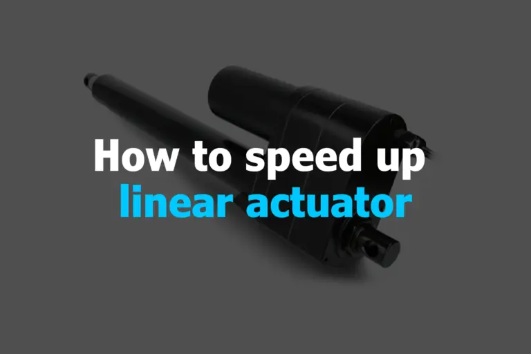
If you’re wondering how to make a linear actuator faster, there are several proven ways to speed up your fast linear actuator safely. You can raise the voltage with proper control, change the gear ratio, get a higher lead screw pitch, or use a motor controller to fine-tune speed. Techniques like PWM control using an Arduino and switching to a high speed actuators type, such as hydraulic or pneumatic, can also help. Regular maintenance, reducing friction, and optimizing the mechanical load can further improve the performance of your fast actuators linear. What is fast linear actuator? A high speed linear actuator 12v is like a super-fast mover in a straight line. Designed to zip back and forth quickly, faster than standard units, these actuators use powerful motors and lightweight materials to move fast while still being accurate and reliable. Fast linear actuators are ideal for applications like robotics and automated machinery where speed and precision are essential. Effective Ways to Speed Up These Device To speed up linear actuator, you can adjust several factors. Increase the voltage to the motor for more power, modify the gear ratio to increase speed, and consider upgrading to a stronger motor. Reducing friction by lubricating moving parts and simplifying the actuator’s design can also help. Characteristics of High-Speed Linear Actuator High-speed linear actuators exemplify swift, precise motion with rapid acceleration and deceleration rates. Compact and lightweight, they boast efficient energy usage, integrating feedback systems for enhanced control. Their durable construction, low inertia, and versatile applications make them ideal for dynamic industrial settings, ensuring reliability, longevity, and ease of integration into diverse automation systems. 7 Ways to Speed Up Linear Actuator Here are 7 proven strategies to make your fast linear actuator operate at optimal speed: 1. Adjusting Voltage Increasing the voltage in a linear actuator can be a dangerous and potentially damaging process if done incorrectly. Before attempting any adjustments, it’s crucial to understand the specific model of your actuator and its capabilities. Improper voltage can lead to overheating, malfunctions, and even electrical shock. Here are some safe and recommended ways to increase the speed of a linear actuator: Pulse Width Modulation (PWM): Many linear actuators use PWM for speed control. Increasing the duty cycle (on-time) of the PWM signal can provide more power and speed within the actuator’s safe operating range. Control signal adjustment: Some linear actuators accept analog or digital control signals. Adjusting the signal within the specified range can increase the speed. Consult the manufacturer’s instructions: The manual or data sheet for your specific actuator should provide detailed information on its voltage range, safe operating limits, and recommended control methods. Never exceed the manufacturer’s recommended voltage for your specific model. Consider alternative solutions: Using a larger or more powerful actuator model may be a safer option than exceeding the voltage limits of your existing one. Gearing can be used to increase the force output of an existing actuator at the cost of reduced speed. Additional Considerations: Wear appropriate personal protective equipment and follow the manufacturer’s safety guidelines. Use specialized tools and techniques if required for precise gear adjustments. If you’re unsure about the process, consult with a qualified technician or contact the manufacturer for assistance. 2. Adjust Gear Ratio While adjusting the gear ratio within a single linear actuator is typically not feasible, here are the common approaches to achieve the desired speed-to-force characteristics for your application: Select the Right Actuator at the Outset: Manufacturers often offer linear actuators with varying gear ratios, each designed to provide specific speed and force combinations. Carefully review the available options to choose the model that best aligns with your project’s requirements. Utilize External Gearing: If necessary, you can install additional external gears to create a custom gear ratio that suits your needs. This approach involves adding gears between the actuator’s output shaft and the driven load. Employ a Motor Controller: For fine-tuning speed control without altering the gear ratio, consider using a motor controller or a linear actuator control board. These devices allow you to adjust the actuator’s speed, end limits, and sensitivity through electronic means. Additional Considerations: Ensure your application can handle the reduced force output before adjusting the gear ratio. Always consult the actuator’s user manual or contact the manufacturer for specific instructions and recommendations regarding gear ratio adjustments or modifications. 3. Lead Screw Pitch The lead screw is a crucial component that converts rotary motion into linear motion. Opting for a lead screw with a higher pitch (distance traveled per screw revolution) results in faster linear movement. Here are key approaches to achieving the desired linear motion speed with a lead screw pitch: Select the Appropriate Actuator: Manufacturers offer linear actuators with varying lead screw pitches. Each influences speed and travel distance per motor revolution. Choose an actuator with a pitch that aligns with your speed and distance requirements. Utilize External Gearing: Employ external gears to modify the effective lead screw pitch. Install a gear train between the actuator’s motor and lead screw to alter the rotational speed and linear travel distance per motor revolution. Control Speed Electronically: For fine-tuning speed without altering the lead screw pitch, use a motor controller or linear actuator control board. These devices adjust motor speed, end limits, and sensitivity, impacting linear motion without physically adjusting the lead screw. Additional Considerations: Lead screw pitch impacts speed and resolution. A finer pitch yields slower speed but higher resolution (smaller incremental movements), while a coarser pitch offers faster speed but lower resolution. 4. Use Motor Controller or LAC Board These devices offer fine-grained control over motor speed, allowing for precise adjustments. Check compatibility with your actuator model before purchasing a controller or board: Compatibility Check: Verify that the controller is compatible with your actuator model and voltage requirements. Consult the controller’s specifications and the actuator’s manual for confirmation. Electrical Connections: Connect the power supply to the controller, ensuring proper voltage and polarity. The linear actuator’s motor wires to the corresponding terminals on the controller. If using external control signals (e.g., switches, sensors), wire them to the appropriate controller inputs. Configuration (if applicable): Some controllers may require programming or
What is a Rotary Actuator and How Does it Work?

Rotary actuators are powered by electricity, fluid pressure, or even manually. They are used in a variety of applications, including valve operation, mobile hydraulic equipment, aircraft, and motion control systems. In a fluid power system, rotary actuators act as output devices, delivering an oscillating motion within a limited range. They generate work through the application of fluid pressure against internal vanes. The choice of rotary actuator depends on the specific application requirements, such as speed, torque, and load capacity. What is a Rotary Actuator? Rotary actuators are a type of mechanical device that uses hydraulics to convert energy into linear motion. They are commonly used in heavy equipment, such as bulldozers, which use them to lift and move heavy objects. Rotary actuators are also used in closed-loop control systems, where they provide high-speed and high-force operation. How Does a Rotary Actuator Work? Fluid Power in Motion Within a fluid power system, rotary actuators function as output devices, delivering an oscillating motion within a limited range (think one full revolution). Right-rotary actuators generate work through direct fluid pressure against internal vanes, utilizing energy over distance. Imagine them as providers of rotating or angular movement – strokes within defined angles – generating a special kind of rotational work called torque. Circuitry Simplified Take a simple rotary actuator circuit diagram, where applied force translates to torque. When these actuators operate at low speeds with high torque, output torque becomes the key parameter for identification and rating. For choosing the right one, speed often takes a backseat to specific application needs. Torque Talk Measuring torque typically involves foot-pounds. For example, a two-foot-radius rotary actuator lifting a 200-pound weight would require 400 lb•ft of torque to do the job. Understanding this system-to-output torque relationship empowers designers to select the perfect actuator for each unique application. Types of Rotary Actuators Manual Rotary Actuator Often using worm drives for amplified torque in manual valve closure, these actuators are common on ball valves and quarter-turn butterflies. Their self-locking capabilities and large hand wheels make them worker-friendly. In the valve industry, they’re sometimes called manual overrides or gear operators. Electric Rotary Actuator Driven by electromagnetic power, electric rotary actuators rotate components. They offer indexing and control capabilities, allowing for multiple position stops with strokes. Their rotating element can be a circular shaft or a table, with shafts often featuring keyways and tables offering bolt patterns for mounting additional components. Specifications include voltage supply, maximum torque, repeatability, load capacity, operating temperature, rotation angle, and linear stroke. These actuators find diverse applications, from high-power switching gears to the automotive industry and packaging. Fluid-Powered Rotary Actuators Also known as pneumatic or hydraulic rotary actuators, these utilize fluid power delivered to cylinders to shift scotch yokes and rack-and-pinion assemblies or to rotors for straight shaft actuation. They typically move between 90° and 360° stops, based on the specific component or valve’s rotation requirements. Rack and Pinion Rotary Actuators These mechanical devices primarily control dampers or valves in industrial settings. The rack & pinion, a couple of gears, converts linear motion to rotational. A linear gear bar (the rack) connects teeth on a round gear (the pinion). When linear force is applied to the rack, the pinion rotates. Scotch Yoke Rotary Actuators This actuator features a sliding bar connected to a valve at one end and a yoke at the other, which includes a slot for a block that slides back and forth. The block is connected to a piston, so when the piston moves, the block drives the yoke, turning it and moving the bar to open the valve. Applications include oil and gas (valve activation for flow separation), mining (valve activation for separating nozzles), and water and wastewater (valve activation for separating feed lines, tanks, and filters). Helical Actuators Using a set of helical gears and a cylinder, this actuator converts linear input to an oscillating, rotary output. The cylinder contains three rotating pins and three helical slots machined within the outermost tube, which also features three keys to prevent excessive movement. When the cylinder moves, air force pushes down on the outermost cylinder for valve opening and squeezes a spring. When the air force is released, the spring pushes the valve to close again. Vane Rotary Actuator These combine the muscle of pressurized hydraulic fluid with the control of an electric motor. The electrical energy powers the motor, which controls a hydraulic pump that supplies the pressurized fluid for operating the valve. This self-contained system eliminates the need for a separate hydraulic power unit, simplifying design and enhancing reliability and safety. Vane Variety Pneumatic and hydraulic vane actuators use one or two vanes connected to a hub in a circular chamber or wedge shape, allowing vane rotation from 90 to 280 degrees. In these actuators, the hub simply rotates between stops using oil or air force to generate motion at the output stem. A double-vane actuator includes two opposite vanes for more torque but limited rotation compared to a single-vane actuator within a full circular chamber. Vane actuators are space-efficient and often used for transferring, clamping, or placing light loads in medium-speed applications. Pros and Cons of Rotary Actuators Rotary actuators, despite their versatility, come with their own set of advantages and disadvantages. Here’s a breakdown to help you decide if they’re the right fit for your application: 1. Advantages Durable and Powerful Rotary actuators boast exceptional durability and deliver relatively high torque for their size, minimizing maintenance needs. Angular Agility Their rotational capabilities allow them to move objects smoothly through any desired angle, offering greater flexibility compared to linear actuators. Stable Performance Once activated, rotary actuators maintain excellent stability even at low speeds, ensuring consistent operation. Smooth Motion They provide smooth acceleration and deceleration, making them ideal for applications that require precise control of movement. Easy Adjustments Rotary actuators equipped with stepping motors allow for simple adjustments in speed and position, enhancing their adaptability. 2. Disadvantages Torque Limitations Vane actuators, a common type, have limited torque and rotation compared to
How to Mount a Linear Actuator?

Linear actuators are the invisible heroes of the industrial world, tirelessly driving automation across countless applications. But even the most robust actuator is rendered useless without a secure and stable mount. At Maxim Systems, we understand the critical role mounting plays in maximizing performance and longevity. This comprehensive guide delves into everything you need to know about how to mount a linear actuator, from choosing the right method to ensuring optimal installation. Understanding the Mounting Landscape The world of actuator mounting offers several methods, each catering to specific needs. Let’s explore the most common options. Clevis Mounts These versatile U-shaped brackets reign supreme in popularity, offering simplicity and flexibility. Clevis mounts allow free rotation and pivoting, making them ideal for applications requiring adaptability. Shaft Mounts Precision is paramount in applications like CNC machines. That’s where shaft mounts shine. Securing the actuator shaft directly to the surface, they eliminate misalignment concerns, guaranteeing precise linear movement. Foot Mounts When heavy-duty applications demand maximum stability, foot mounts rise to the challenge. Bolting directly to the actuator housing, they offer a robust platform for distributing high loads evenly. Trunnion Mounts Need the actuator to operate at an angle? Look no further than trunnion mounts. These robust mounts feature two trunnion brackets attaching to the shaft, enabling rotation in one direction. Custom Mounting Solutions For unique applications, custom mounting solutions may be the answer. Maxim Systems offers expertise in designing and fabricating bespoke mounts, ensuring your actuator thrives in even the most challenging environments. Choosing the Perfect Mount Finding the ideal mounting solution hinges on understanding your application’s specific needs. Here are the key factors to consider: Load: The weight and force the actuator will encounter. Stroke: The required distance the actuator needs to travel. Speed: The desired operating speed of the actuator. Precision: The demanded level of accuracy for the actuator’s movement. Environmental Factors: Will the actuator be exposed to dust, moisture, or other harsh conditions? How to Mount a Linear Actuator: A Step-by-Step Guide Now that you’ve chosen the perfect mounting method and considered your application’s specific requirements, it’s time to get hands-on and install your linear actuator. Follow these step-by-step instructions for a smooth and successful process: 1. Gather Your Tools and Materials Linear actuator and mounting brackets: Ensure you have the correct components for your chosen mounting method. Safety equipment: Wear gloves, safety glasses, and any other necessary protective gear. Appropriate tools: Depending on your mounting method, you might need wrenches, screwdrivers, a drill, and other tools. Leveling tool: A spirit level helps ensure precise alignment for optimal performance. Marking tools: A marker or pen helps mark mounting points and ensure accuracy. 2. Prepare the Mounting Surface 3. Attach the Mounting Brackets Align the mounting brackets with the pre-drilled holes or designated mounting points on the actuator. Secure the brackets using the appropriate bolts, screws, and washers. Ensure they are tightened to the manufacturer’s recommended torque specifications. For clevis mounts, insert the clevis pin through the holes on the actuator and the bracket, securing it with a cotter pin or retaining clip. 4. Position the Actuator Carefully lift the actuator and position it within the mounting brackets. Ensure proper alignment of the shaft or mounting points. Make any final adjustments for alignment and ensure the actuator sits securely within the brackets. 5. Secure the Actuator For foot mounts and other stationary mounts, tighten the bolts or screws that secure the actuator directly to the mounting surface. Double-check all connections and ensure everything is secure and stable. 6. Connect Electrical Components (if applicable): If you’re using a motorized actuator, carefully connect the electrical wires according to the manufacturer’s instructions. Double-check all connections for proper polarity and ensure they are safe and secure. 7. Test and Verify Before applying any load, power on the actuator and observe its movement. Check for any abnormal sounds, vibrations, or binding. If using a clevis mount, ensure the pin is properly seated and the actuator moves freely within the brackets. Once satisfied with the operation, you can proceed to apply the intended load and operate the actuator as required. Maximizing Mounting Efficiency Once you’ve chosen your mounting method, meticulous installation is crucial for optimal performance. Here are some key tips for maximizing mounting efficiency: Regular maintenance, including checking the tightness of connections and inspecting for wear and tear, is essential for ensuring optimal performance and the long life of your linear actuator. If you encounter any challenges during the installation process, consult a qualified technician for assistance. Maxim Systems: Your Partner in Linear Actuator Solutions At Maxim Systems, we’re your trusted partner in the world of linear actuators and mounting solutions. We offer a comprehensive range of actuators and mounting accessories, catering to diverse applications. Our team of experts is here to assist you in selecting the right products and providing technical support throughout your project. Contact us today and unlock the full potential of your linear actuators!
How To Calculate Linear Actuator Position?
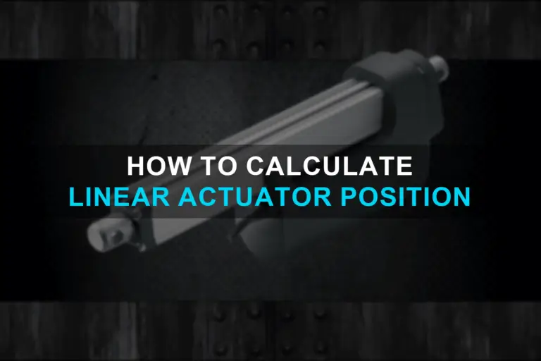
To precisely control a linear actuator‘s movement, calculating its position is key. This involves three crucial pieces of information: the actuator’s total travel distance (length), its starting point, and the desired final position. With these values in hand, a simple formula unlocks the secret: Position = (Final Position – Starting Position) / Length of Actuator. In essence, calculating the position clarifies the exact distance the actuator needs to travel to reach its designated endpoint. Mastering this calculation empowers you to program precise movements, ensuring your project operates with optimal efficiency and achieves flawless results. Demystifying Linear Actuator Position Calculations In the realm of industrial automation, linear actuators play a pivotal role in transforming rotary motion into linear motion, powering a wide range of applications from simple opening and closing mechanisms to complex robotic systems. Understanding how to calculate linear actuator position is crucial for ensuring precise control and achieving desired outcomes in these applications. The Basics Before diving into the calculations, let’s establish the fundamental concepts that underpin linear actuator position determination. The position of a linear actuator refers to the distance its rod or shaft has extended from its fully retracted position. This distance is typically measured in millimeters (mm) or inches (in). Dimensions The dimensions, displayed on the left side of the calculator, represent the information you input to specify your particular application. You can modify these values to determine a suitable linear actuator with appropriate mounting positions. Box Width The box width, measured in inches, indicates the width of the space underneath your hatch. This value may influence the physical size of a suitable linear actuator depending on the mounting positions. Typically, it corresponds to the width of the lid itself, but in some cases, you may have more space beneath the lid than its width. Box Height The box height, measured in inches, represents the depth of the space underneath your hatch. This value is particularly crucial when space beneath the hatch is limited, such as with a tonneau cover on a pickup truck, as it will restrict the physical size of a suitable linear actuator. When there is ample space underneath the lid, like with a trapdoor to a cellar, the box height becomes less significant. Lid Weight The lid weight, measured in pounds, represents the weight of the lid you intend to open or the size of the load you plan to rotate. Naturally, this value will significantly impact the selection of an appropriate linear actuator for your application. Max Angle The max angle, ranging from 0 degrees (closed) to 90 degrees, indicates the maximum angle at which your lid will open. Once again, this value will have a substantial influence on the potential linear actuators available for your application. Lid Mount Position The lid mount position, measured in inches, represents the location where your linear actuator will be attached to the lid. This value can vary from 0 inches to the box width or the end of the hatch. If you have flexibility in mounting the linear actuator to the lid, you can adjust this value to find results that best suit your application. However, in certain applications, the position where you can mount the linear actuator to the lid may be restricted. Actuator Type The actuator type refers to the type of actuator you intend to use. Your choice of actuator type may depend on your application or desired features, such as feedback options. You can explore the various types of linear actuators available in our store to determine which one is best for you. If you’re not particular about the type, you can experiment with different actuator types in the calculator to identify the one that best meets your needs. Choose Actuator Once you select a specific actuator type, you will then choose an actuator of that type with a particular stroke length. Since you may be unsure of the required stroke length, you can easily try out different lengths to determine if that particular actuator will fit your needs. Number of Actuators The number of actuators indicates the quantity of actuators involved in your application. While you can select either 1 or 2, the calculator will default to recommending using 2 actuators (one mounted on either side of the hatch) as it provides greater stability. It is never advisable to push a hatch open from just one side. We do offer the option to change to 1, but only do this if you are mounting the actuator in the center of the hatch. Factors Influencing Linear Actuator Position Several factors influence the position of a linear actuator, including: Calculating Linear Actuator Position Now that we’ve grasped the fundamental concepts, let’s delve into the practical aspect of calculating linear actuator position. The primary formula for calculating linear actuator position is: Position = Stroke × Extension Percentage Where: Example Calculation: Consider a linear actuator with a stroke of 100 mm and an extension percentage of 50%. Applying the formula, we get: Position = 100 mm × 0.5 = 50 mm Therefore, the actuator’s rod or shaft has extended 50 mm from its fully retracted position. Real-World Applications: Bringing Calculations to Life Linear actuator position calculations play a crucial role in various real-world applications, such as: Unveiling the Power of Precision Understanding how to calculate linear actuator position empowers engineers and technicians to make informed decisions regarding the selection, control, and optimization of these versatile components. By mastering these calculations, you can harness the power of linear actuators to achieve precise positioning, enhance automation processes, and optimize motion control systems. Embark on this journey of precision and unlock the full potential of linear actuators in your industrial endeavors! To get a full picture on how to install a linear actuator, read this blog.
How Does a Linear Actuator Work?

Linear actuator is an actuator which helps enabling tasks like lifting, positioning, or adjusting machinery with accuracy and control in industrial automation, robotics, and manufacturing. A linear actuator works by converting rotational motion into linear motion. It ensures precise movement in a straight line. Linear actuator uses an electric motor, hydraulic, or pneumatic system to create force that pushes or pulls objects. What is a linear actuator? A linear actuator is a device that moves back and forth in a straight line. There are different types of linear actuators, like mechanical actuators use gears, electro-mechanical blend electricity and mechanics, and direct electric actuators called linear motors. Hydraulic and pneumatic actuators use liquids or air to move. The Mechanism Explained While various internal designs exist, the core principle remains the same. At its heart, a linear actuator uses a motor (think electric, hydraulic, or pneumatic) to turn a threaded screw (lead screw). This rotation translates into linear motion as the screw interacts with a nut or piston, pushing or pulling it along its thread. The screw’s pitch (distance between threads) determines the linear distance traveled per motor revolution, offering precise control over movement length. Diversity in Size and Strength Linear actuators aren’t one-size-fits-all solutions. They come in a remarkable range of sizes and configurations, capable of generating forces – from delicate micro-movements to heavy-duty industrial applications. Whether you need to adjust a camera lens with pinpoint accuracy or operate a giant industrial press, there’s an actuator perfect for the job. How Does a Linear Actuator Work? The Motor: The journey begins with the motor, your choice based on the desired force and application (electric, hydraulic, or pneumatic). The Threaded Maestro: The lead screw plays a crucial role. Its pitch dictates the distance traveled per motor revolution, offering precise control. The Force Carrier: The nut or piston receives the force from the screw, translating it into linear movement. Direction Control: Depending on the design, internal mechanisms like switches or valves dictate the direction (forward or backward) of the linear movement. Precision and Control: Feedback mechanisms often provide real-time information about the actuator’s position and speed, allowing for precise control and automated systems integration. Diverse Applications Across Industries Linear actuators power a vast array of industries and applications including: Manufacturing: Precise positioning of robotic arms, material handling, and machine automation. Medical: Adjustable beds, wheelchairs, and surgical equipment for enhanced patient care. Renewable Energy: Tracking solar panels for maximum sun exposure or adjusting wind turbine blades for optimal wind capture. Aerospace: Actuating control surfaces in airplanes and deploying landing gear. Consumer Electronics: Camera lens adjustments in phones and automated furniture adjustments. The possibilities are endless! With their versatility, power, and precision, linear actuators continue to revolutionize diverse sectors, making our lives easier and more efficient. Types of Linear Actuators There are many different types of linear actuators, each with its own advantages and disadvantages. The most common type of linear actuator is the electric linear actuator, which uses an electric motor to drive the screw or lead screw. Electric Linear Actuators Electric linear actuators use an electric motor to drive the screw or lead screw. Electric linear actuators are the most common type of linear actuator, and they are available in a wide range of sizes and configurations. Pneumatic Linear Actuators Pneumatic linear actuators use compressed air to drive the piston or rod. Pneumatic linear actuators are typically used for high-force applications, and they are often used in industrial settings. Hydraulic Linear Actuators Hydraulic linear actuators use pressurized fluid to drive the piston or rod. Hydraulic linear actuators are typically used for high-precision applications, and they are often used in medical devices and aerospace applications. Mechanical Linear Actuators Mechanical linear actuators use a mechanical mechanism, such as a screw, lead screw, or cam, to convert rotational motion into linear motion. Mechanical linear actuators are typically simple and inexpensive, but they may not offer the same level of precision or speed as other types of linear actuators. Piezoelectric Actuators Piezoelectric actuators use the piezoelectric effect to convert electrical energy into linear motion. Piezoelectric actuators are very precise and fast, but they are also relatively expensive and can only generate relatively small forces. Coiled Actuators Coiled actuators use a coiled spring to generate linear motion. Coiled actuators are compact and lightweight, and they can generate high forces, but they can be relatively noisy and have a limited stroke length. Electro-Mechanical Linear Actuators Electro-mechanical linear actuators combine mechanical and electrical components to convert rotational motion into linear motion. Electro-mechanical linear actuators offer a good balance of precision, speed, force, and affordability. Telescoping Linear Actuators Telescoping linear actuators use a series of nested tubes to extend their stroke length. Telescoping linear actuators are ideal for applications where a long stroke length is required, but they can be relatively bulky and expensive. Ball Slide A ball slide is a linear actuator that uses a series of ball bearings to achieve smooth and precise linear motion. Ball slides are often used in applications where high precision and repeatability are required, such as in medical devices and semiconductor manufacturing. Other Types of Linear Actuators In addition to the types of linear actuators described above, there are other types of linear actuators available – including Rotary Linear Actuators, Linear Slide Actuators, Linear Rod Actuators, Linear Piston Actuators, and Linear Motor Actuators. Components of a Linear Actuator Linear actuators are made up of a number of different components, including – Motor The motor provides the rotational force that is converted into linear motion. Electric linear actuators use an electric motor, while pneumatic linear actuators use compressed air, and hydraulic linear actuators use pressurized hydraulic fluid. Screw or Lead Screw The screw or lead screw is the threaded rod that converts rotational motion into linear motion. It is important to choose a screw or lead screw with the appropriate pitch and thread form for your application. Nut The nut travels along the screw or lead screw to convert rotational motion into linear motion. It is important to choose a nut that is made of a durable material and that is the correct size for
How To Install A Linear Actuator

A linear actuator is a device that converts electrical energy into mechanical motion. It consists of a motor, a lead screw, and a nut. The motor turns the lead screw, which in turn moves the nut along the length of the actuator. How Does a Linear Actuator Work? The motor in a linear actuator is typically a DC motor. DC motors are very efficient and can provide a high torque output. This makes them ideal for applications that require a lot of force, such as lifting and positioning heavy objects. The lead screw in a linear actuator is a threaded rod. The nut in the actuator is threaded to match the lead screw. When the motor turns the lead screw, the nut moves along the length of the actuator. This causes the load that is attached to the nut to move as well. Different Types of Linear Actuators There are two main types of linear actuators: electric linear actuators and pneumatic linear actuators. Electric linear actuators are the most common type of linear actuator. They are powered by electricity and are relatively easy to install and operate. Pneumatic linear actuators are powered by compressed air. They are more powerful than electric linear actuators, but they are also more complex and expensive. Choosing The Right Mounting Method for Your Linear Actuator The best way to choose the right mounting method for your linear actuator is to consider the specific needs of your application. Factors to consider include the actuator’s load capacity, stroke length, and range of motion. You should also consider the environment in which the actuator will be operating, as well as the budget and resources available to you. Clevis Mounting Clevis mounting is the most common mounting method for linear actuators. This method allows the actuator to pivot on both sides, which is useful for applications where the actuator needs to be able to move freely. Clevis mounting is also relatively simple and inexpensive to implement. Stationary Mounting Stationary mounting is another common mounting method for linear actuators. This method fixes the actuator in place, which is useful for applications where the actuator needs to provide a precise and stable force. Stationary mounting is also relatively simple to implement, but it does not allow the actuator to pivot. Trunnion Mounting Trunnion mounting is a less common mounting method for linear actuators. This method allows the actuator to rotate about a fixed point, which is useful for applications where the actuator needs to move in a circular or elliptical path. Trunnion mounting is more complex and expensive to implement than clevis or stationary mounting, but it offers greater flexibility in terms of actuator movement. Flange mounting This method uses flanges to attach the actuator to a mounting surface. Flange mounting is strong and durable, but it can be more complex and expensive to implement than other mounting methods. Foot mounting This method uses feet to attach the actuator to a mounting surface. Foot mounting is simple and inexpensive to implement, but it is not as strong or durable as flange mounting. Rod-end mounting This method uses rod ends to attach the actuator to a mounting surface. Rod end mounting is simple and inexpensive to implement, and it allows the actuator to pivot on both sides. Direct mounting This method involves directly attaching the actuator to a mounting surface without using any mounting brackets. Direct mounting is strong and durable, but it can be more difficult to implement than other mounting methods. How to Choose the Right Linear Actuator When choosing a linear actuator for your application, there are a few key factors to consider. Stroke length: The stroke length is the distance that the actuator can travel. Choose an actuator with a stroke length that is slightly greater than the distance that your load needs to travel. Force rating: The force rating is the maximum amount of force that the actuator can exert. Choose an actuator with a force rating that is greater than the weight of your load. Speed: The speed is the rate at which the actuator can move. Choose an actuator with a speed that is appropriate for your application. Duty cycle: The duty cycle is the percentage of time that the actuator can be operated at its full force rating. Choose an actuator with a duty cycle that is greater than the amount of time that you will be using it at full force. How to Install a Linear Actuator: A Step-By-Step Guide Additional Tips on Installing a Linear Actuator
Maxim Systems: Pioneering Industrial Automation Needs

Maxim Systems is the premier destination for all your industrial automation needs. Since our company’s beginning in 2001, we have been driven by a core belief in prioritizing our customers above all else. Our commitment to exceptional customer service, technical expertise, and application assistance has made us a trusted name in the industry. At Maxim Systems, we offer a truly dynamic range of pneumatic products and related services, all designed to optimize your automation processes and elevate your business to new heights. Why Choose Maxim Systems for Your Industrial Automation Supplies Maxim Systems works with over a 100 industrial automation product manufacturers, and has the ultimate collection of industrial automation solutions. In addition, our highly expert engineers will help you choose the right products for your business, and offer any technical support that you may require after a purchase. Unparalleled Customer Service Maxim Systems is a consumer-focused company, and we do everything we can to deliver the most attractive services to our clients. We take pride in being able to address your needs and help you meet your goals. Our team of experts are devoted to bring you the best customer experience that you truly deserve! The Right Guidance Whether you need help selecting the right pneumatic products or need help with the optimization of your industrial automation process, Maxim Systems is here to guide you across the entire customer journey. We also help solve all your technical difficulties and offer other relevant services. Vast Inventory Cutting back on downtime is imperative when it comes to Industrial Automation.At Maxim Systems, we maintain a well-stocked inventory of top-notch fluid power, motion control, and machine safety components, readily available to meet your urgent needs. With our local stock, you can trust that the products you require are just a call away. Commitment to Quality and Support We never compromise with quality and both source and deliver only high quality products. When you choose Maxim Systems as your vendor, you gain access to world-class products from renowned manufacturers. Our dedication towards service extends beyond sale, as we deliver after sales service and technical support. Tailored Solutions for Clients We understand that every automation project is unique, which is why we work with a huge selection of leading manufacturers to bring you the best-in-class solutions that best fit your requirements. Manufacturers We Work With Maxim Systems is a one stop solution for all your industrial automation needs. We work with all the top names in the industry Here’s a list of some manufacturers we collaborate with. ACE is a leading provider of motion control products, including servo drives, motors, and encoders. Their products are used in a wide range of applications, from manufacturing to robotics. ATU is a global supplier of pneumatic components, such as valves, cylinders, and fittings. Their products are used in a variety of industries, including manufacturing, packaging, and healthcare. ADSENS is a manufacturer of sensors, such as proximity sensors, encoders, and vision sensors. Their products are used to automate a wide range of processes, from machine vision to quality control. Alkon Corporation is a manufacturer of industrial valves, actuators, and controls. Their products are used in a variety of applications, including oil and gas, food and beverage, and water treatment. Apex Dynamics, USA is a manufacturer of linear actuators, rotary actuators, and precision motion control systems. Their products are used in a variety of industries, from machine tools to medical devices. ATP is a leading manufacturer of electrical connectors, such as terminal blocks, wire harnesses, and cable assemblies. Their products are used in a wide range of applications, from industrial automation to automotive. Belden is a global leader in the development and manufacture of electrical cables and wires. Their products are used in a variety of industries, including telecommunications, transportation, and energy. Canfield Connector is a manufacturer of industrial connectors, such as electrical connectors, pneumatic connectors, and hydraulic connectors. Their products are used in a variety of applications, from automation to medical devices. CONTRINEX is a leading manufacturer of safety switches, sensors, and controls. Their products are used to protect people and property in a variety of industries, from manufacturing to healthcare. Daughtridge Sales is a distributor of industrial automation products, such as motion control products, sensors, and valves. They offer a wide range of products from leading manufacturers. EDCO USA is a manufacturer of pneumatic components, such as valves, cylinders, and fittings. Their products are used in a variety of industries, from manufacturing to packaging. Fabco Air is a manufacturer of pneumatic components, such as valves, cylinders, and fittings. Their products are used in a variety of industries, from manufacturing to packaging. HELUKABEL is a global leader in the development and manufacture of electrical cables and wires. Their products are used in a variety of industries, including telecommunications, transportation, and energy. HIWIN is a manufacturer of linear motion components, such as linear guides, ball screws, and actuators. Their products are used in a variety of applications, from machine tools to medical devices. Hofmann Fluid is a manufacturer of hydraulic components, such as pumps, valves, and cylinders. Their products are used in a variety of industries, from manufacturing to construction. HTM Sensors is a manufacturer of sensors, such as proximity sensors, encoders, and vision sensors. Their products are used to automate a wide range of processes, from machine vision to quality control. IAI AMERICA is a manufacturer of robotic arms, vision systems, and machine vision software. Their products are used in a variety of industries, from manufacturing to healthcare. JVL is a manufacturer of industrial valves, actuators, and controls. Their products are used in a variety of applications, from oil and gas to food and beverage. LUTZE is a manufacturer of electrical connectors, such as terminal blocks, wire harnesses, and cable assemblies. Their products are used in a wide range of applications, from industrial automation to automotive. MENCOM is a manufacturer of pneumatic components, such as valves, cylinders, and fittings. Their products are used in a variety of industries,