How Does an Air Operated Valve Work? A Simple Guide
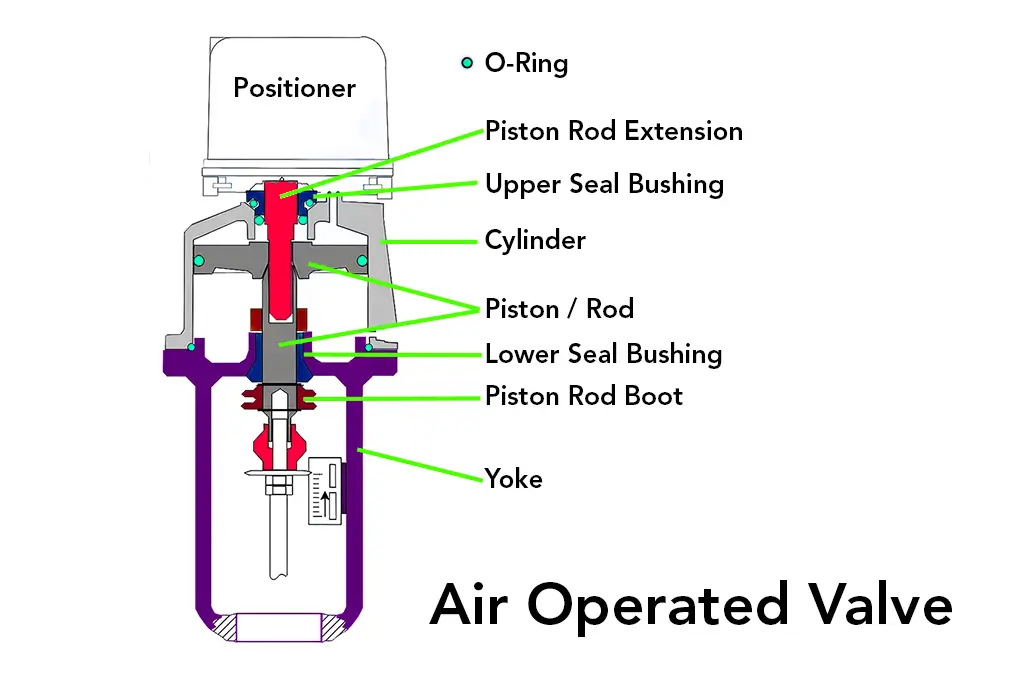
An air-operated valve, also known as a pneumatic valve, plays an important role in industries where the flow of any fluid or gas needs to be controlled. These valves are widely used in applications like manufacturing and chemical processing, among other fields. But how does an air-operated valve work? In this blog, we’ll break it down to a simple explanation of its operation mechanism, the need, and why they are important. What is an Air Operated Valve? The air-operated valve, sometimes called the pneumatically operated valve, is one that uses compressed air for operation-opening, completely shutting, or regulating liquids or gases in a pipeline. As opposed to a manual valve, which would require physical energy, these air operated valves depend on pneumatic energy, hence making them more effective and efficient in a number of uses when applied industrially. They are ideal for operations that require being remotely operated, high-pressure systems, and those places where both precision and speed are needed. Based on the design and application, these valves can be used either for on/off control or for modulating flow. How Does an Air-Operated Valve Work: Step-By-Step To understand how does an air operated valve work, let’s break it down step by step: The Role of Compressed Air The Major Source in the running of air operated valves is compressed air. Compressed air is supplied thru a pneumatic system down to the valve’s actuator. The actuator is that part of the valve responsible for converting pneumatic energy to mechanical motion. The Actuator The actuator is considered the heart of the air-operated valve, as it decides whether the valve should open, close, or stay in a partially open position. Two major types of actuators that may be used in air-operated valves are as follows: Valve Operation The action of the valve is described based on the actuator type and design of the valve. Here’s a basic explanation of how that process works: Types of Air Operated Valves There are several types of air-operated valves available, each designed for different applications. They include: 1. Air Operated Ball Valves These types of valves use a ball with a hole in the middle. The actuator rotates the ball. It either aligns the hole with the pipeline for flow or blocks it to stop the flow. 2. Air-Operated Butterfly Valves Butterfly valves use a rotating disc to regulate flow. They are lightweight, compact, and ideal for large-diameter pipelines. 3. Air-Operated Diaphragm Valves These valves are equipped with a flexible diaphragm that travels up or down depending on the flow of fluids. They serve well in handling corrosive or viscous fluids. 4. Air-Operated Globe Valves Globe valves have a linear motion design, hence are suitable for applications involving precise flow regulation. Find the details and wide range of air operated valves on MaximSystems. How To Choose the Right Air Operated Valve The proper selection of the appropriate air-operated valve in an application would take due regard for the following considerations: Advantages of Air Operated Valves There are numerous advantages offered by air-operated valves, which make them popular in industries: 1. High Efficiency Pneumatic systems move at incredible speed, hence ensuring opening and shutting of the valves very fast. 2. Safe Operations Since these kinds of valves use compressed air instead of electricity or human effort, they are safe to handle in hazardous conditions. 3. Remote Control Air-operated valves have the option for remote operation. Thus, operators may be located at a safer distance when operating systems. 4. Flexibility Compatible with many types of fluids and gases in a wide operating range of conditions, making them adaptable to many industry needs. 5. Little Maintenance With fewer moving parts compared to other valve types, air-operated valves require less maintenance, therefore reducing downtime and costs. Conclusion So, how does an air-operated valve work? Well, essentially, it regulates the flow of liquids or gases through a pipeline using compressed air. The actuator converts air pressure to mechanical motion that allows a valve to open, shut, or adjust the flow of a medium. From water treatment and manufacturing, among many industries, air-operated valves are versatile, efficient, and reliable. Having explained the working mechanism, the types, and applications of air-operated valves, you will go a long way in securing a better decision on their inclusion within your systems. If you would like to upgrade your process in industry, air-operated valves are a sensible choice for increasing efficiency and safety.
Understanding: What is a Direction Control Valve and How Does It Work?
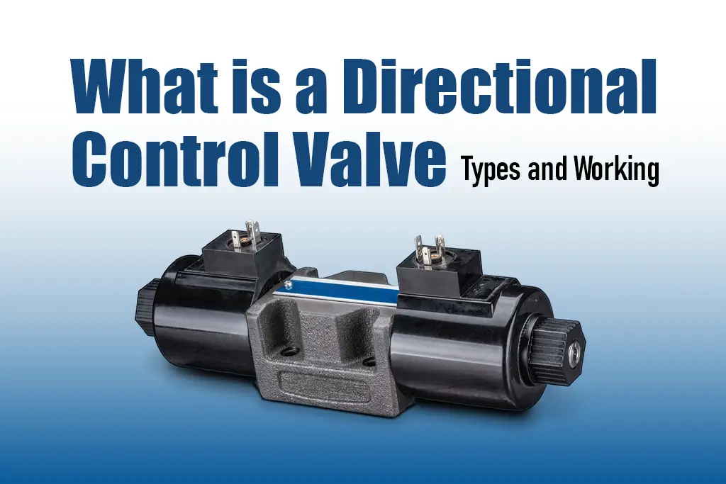
Directional control valves are some of the most vital valves in the industry. They are used in directing air flow, liquids, and hydraulic fluids within machines to ensure all operations run well and effectively. This blog will highlight what is a direction control valve, how they operate, and why they are valuable. What is a Direction Control Valve? The direction control valve refers to a device that directs the flow of fluid or air in a system. It decides where the fluid (such as hydraulic oil or compressed air) goes and how it gets there. Just as a traffic controller helps traffic move in the right direction at the right time, a directional control valve does so for fluids. Directional control valves are widely used in hydraulic and pneumatic systems. including machinery such as forklifts, factory automation equipment, and even airplanes. How Does a Direction Control Valve Work? The valve works by opening and closing internal passages to control the flow of fluid or air. It has several ports (openings) where fluid enters and exits. By shifting the valve’s internal parts, it can: The hydraulic directional control valve is used in systems that rely on pressurized liquids, while an air directional control valve is used in systems powered by compressed air. Both types function similarly but are designed for different mediums. Types of Direction Control Valves There are several kinds of directional control valves, each for specific tasks. Below are some common ones: Hydraulic Directional Control Valves These directional hydraulic control valves are used in hydraulic systems where liquids serve as the working fluid. They are commonly used in heavy construction equipment, such as excavators, which ultimately drive arms and buckets. Pneumatic Directional Control Valves These valves are designed for systems that use compressed air. You’ll see these in industries like packaging or food processing, where quick and precise movements are required. Manual, Solenoid, and Pilot-Operated Valves Why Are Direction Control Valves Important? Choosing the Correct Directional Control Valve Selection of a Direction Control Valve Depends On: Conclusion A valve directional control is a crucial element within hydraulic and pneumatic systems, as it ensures that the movement of fluids or air is in a correct manner so that the machines work efficiently and safely. Whether you need a hydraulic directional control valve for heavy machinery or an air directional control valve for industrial automation, the right choice of a valve is critical for seamless operations.
Step-by-Step Guide to Calculating Pneumatic Cylinder Force
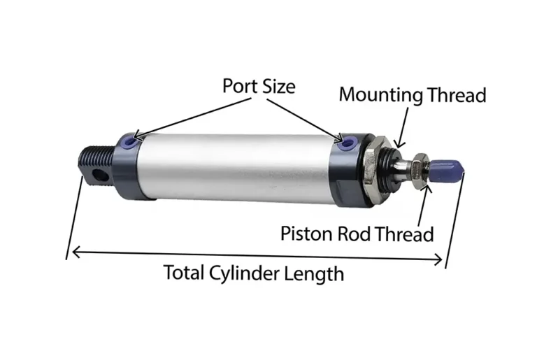
Pneumatic air cylinders are crucial in various industrial applications to create linear motion using compressed air. It’s important to calculate pneumatic air cylinder force accurately to ensure that these cylinders perform effectively. This blog will guide you through the methods for calculating the force of pneumatic air cylinders, specifically focusing on how to use a calculator for these calculations. What is a Pneumatic Air Cylinder? A pneumatic air cylinder is a device that converts compressed air energy into linear motion to perform tasks such as lifting heavy objects or operating machinery. The main body where the piston moves is the cylinder. The component that moves inside the cylinder creates force is the piston and end caps seal the chambers and allow compressed air to enter or exit. When compressed air enters one side of the piston, it pushes the piston to the other side which creates movement for lifting, pushing, or pulling. Pneumatic air cylinders are widely used in automotive, packaging, and robotics industries. Why You Need To Calculate Pneumatic Air Cylinder Force? Pneumatic air cylinders convert compressed air into mechanical force which allows them to perform tasks like pushing, pulling, or lifting. Understanding how force is generated and calculating the force of a pneumatic air cylinder is crucial for several reasons: How to Calculate the Force of a Pneumatic Air Cylinder To calculate the force of a pneumatic air cylinder, you can use the following formula: The Force Formula Force (F)= Pressure (P) × Area (A) Where: Step 1: Gather Required Information You need: Measure Pressure in PSI 1. Using a Pressure Gauge: 2. Using an Electronic Pressure Sensor: 3. Consult System Specifications: Measure the Diameter of the Piston in Inches 1. Using a Caliper: 2. Using a Ruler or Tape Measure: 3. Referencing Manufacturer Specifications: Step 2: Calculate the Area (A) To find the area of the piston, use the formula for the area of a circle: A = πr2 This formula looks complicated, but it’s simple when you break it down: Here we got A(area) = 12.56 Step 3: Input Pressure Let’s take, Pressure (P) = 80 PSI (as an example) Step 4: Calculate the Force (F) After getting the P(pressure) and A(area) we can easily find F(force) Now use the force formula: F= (P×A) Using a Calculator: Here we got, Now, multiply the Pressure by Area: F = (P×A) F = (80 × 12.56) F = 1004.8 pounds Thus, the force generated by this pneumatic air cylinder is approximately 1004.8 pounds. Summary of Steps to Calculate Pneumatic Air Cylinder Force Key Considerations for Pneumatic Air Cylinder Force Calculation Conclusion Calculating the force of a pneumatic air cylinder is a vital step in ensuring its efficiency and effectiveness in various applications. By understanding the key factors involved—such as piston diameter, air pressure, and cylinder type—you can make informed decisions that enhance the performance of your pneumatic system. While online calculators are useful for quick estimates, they may not always provide accurate results due to varying conditions and input errors. It’s best to use them as a starting point and consider manual calculations or expert advice for important applications. This approach will help you optimize your pneumatic system for reliability and performance.
How Does a Rodless Cylinder Work: Step-By-Step
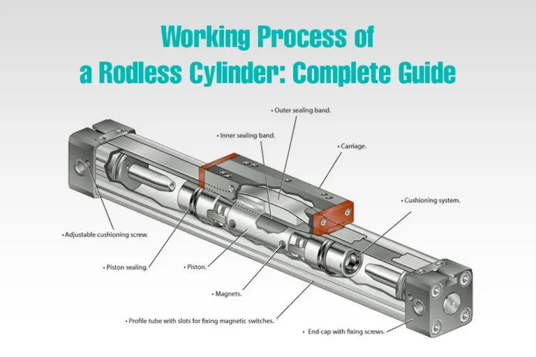
A rodless cylinder is a type of pneumatic cylinder that operates without an external piston rod. Instead, it has an internal piston mechanism that moves along the length of the cylinder body, with the load attached directly to the cylinder. In this article, you will learn how does a rodless cylinder work and how you can select the right rodless cylinder for your application. Different Types of Rodless Cylinder There are several types of rodless cylinders used across many industries. Slotted-type Rodless Cylinder, Magnetic Cylinder, Magnetically Coupled Rodless Cylinder and Cable Rodless Cylinder. A slotted-type rodless cylinder is more specialized in terms of its function and value. 1. Slotted-Type Rodless Cylinder A slotted-type rodless cylinder features a slot running along its length. This slot allows the internal piston to be connected to an external carriage, which moves along the external surface of the cylinder. The design enables the cylinder to achieve linear motion without an extending piston rod, making it highly suitable for applications with limited space. 2. Magnetic Rodless Cylinder A magnetic rodless cylinder is a type of pneumatic cylinder designed to provide linear motion without the use of an external piston rod. It employs a magnetic coupling mechanism to transfer the motion of the internal piston to an external carriage. Magnetic rodless cylinder allows for a compact and efficient use of space which makes magnetic rodless cylinders ideal for various industrial applications where space constraints and smooth operation are crucial. 3. Magnetically Coupled Rodless Cylinder A magnetically coupled rodless cylinder provides linear motion without the need for an External Piston Rod. It uses a magnetic coupling between the internal piston and an external carriage to transfer the motion. 4. Cable Rodless Cylinder A cable rodless cylinder provides linear motion without an Extending Piston Rod. It uses a cable system to transfer the motion of the internal piston and an external carriage. This design is highly space-efficient and ideal for applications requiring long stroke lengths in confined spaces. How Does a Rodless Cylinder Work? (Explained) A rodless cylinder works by providing linear motion without the need for an extending piston rod. A rodless cylinder uses compressed air to move an internal piston, which in turn moves an external carriage along the cylinder’s length. Here’s a simplified explanation of how does a rodless cylinder works. 1. Internal Piston Movement There is an internal piston inside the Sealed Cylinder that moves back and forth when compressed air is applied to either side of it. The application of air pressure moves the piston in a linear direction. 2. Connecting the Piston to the Carriage The piston inside the cylinder is connected to the carriage outside in one of these ways: 3. External Carriage The external carriage, which is mounted on the outside of the cylinder, moves along the length of the cylinder as the internal piston moves. The carriage is directly or indirectly connected to the internal piston. 4. Moving the Carriage When air pressure pushes the piston back and forth, the piston moves the carriage along the cylinder. This external carriage carries the load or object you need to move. 5. Sealed Environment The cylinder is sealed to maintain air pressure and prevent contaminants from entering. This ensures efficient operation and longevity of the cylinder. Pros and Cons of Using a Rodless Cylinder Using a rodless cylinder has many advantages for your application but it also comes up with some limitations. Here are some pros and cons you can keep in mind: Pros: Cons: Things To Consider While Choosing a Rodless Cylinder Piston Stroke Length: This is how far the cylinder can move back and forth. Make sure it’s long enough for your needs. Load Capacity: Consider how much weight the cylinder can handle. If you’re lifting something heavy, you’ll need a cylinder that’s strong enough. Speed: Some cylinders are quicker than others, so choose one that matches your speed requirements. Mounting Options: Check how you can attach the cylinder to your machine or equipment. Different cylinders have different mounting options, so make sure it fits. Space: Rodless cylinders can save space because they don’t have a rod sticking out. Think about how much room you have for the cylinder to move. Seals and Protection: Look for cylinders with good seals to keep out dust and dirt. This helps the cylinder last longer and work better. Maintenance: Consider how easy it is to maintain the cylinder. Some might need more upkeep than others, so think about what you can handle. Budget: Lastly, think about your budget. rodless cylinders come in different price ranges, so find one that fits your budget while still meeting your needs. Where Rodless Cylinders Are Commonly Used Rodless cylinders are used in various industries where precise and space-efficient linear motion is needed, such as: Manufacturing: For moving parts along a production line. Packaging: For handling packages in automated systems. Automotive: For positioning parts during assembly. Medical Devices: For moving components in clean, controlled environments. Robotics: For providing precise motion in robotic arms and other automated systems. Conclusion Rodless cylinders provide a versatile and efficient solution for linear motion applications. Their compact design, long stroke capabilities, smooth and precise movement, and reduced maintenance make them a valuable component in many industrial and commercial settings. By offering space efficiency, high load capacity, and energy savings, rodless cylinders are an excellent choice for optimizing performance in various applications.
What is a rotary indexing table and how does it work?

Rotary indexing tables are widely used in Automotive Manufacturing. Electronics Production. Medical Device Fabrication, Food and Beverage Packaging, and Aerospace Component Manufacturing industries. In this article, we will discuss everything about What is a rotary indexing table and how does work it. What is a Rotary Indexing Table? A rotary indexing table is a mechanical device used mainly in manufacturing and automation to facilitate the sequential processing of workpieces. It typically consists of a circular platform with multiple workstations positioned around its perimeter. The main function of a rotary indexing table is to rotate incrementally, bringing each workstation into position for the assigned task. At each workstation, specific manufacturing operations such as drilling, milling, assembly, or inspection are performed on the workpiece as it progresses through the production process. Features of Rotary Indexing Table Rotary indexing tables have multiple workstations equipped with several stations around its borders. It moves stepwise to align workpieces accurately at each station for efficient handling and helps with various tasks like drilling, milling, and assembly. Easy Customization Adapting to diverse production needs. You can easily customize its size, station count, and configuration to fit specific manufacturing requirements. Built Materials Rotary indexing tables are built from durable materials for longevity and reliability in industrial settings, which enable the optimization of workstation activities for maximum productivity through advanced control mechanisms. It helps in areas where material loading and unloading is concerned, further improving workflow efficiency. It incorporates emergency stop buttons and protective guards to prioritize operator safety in manufacturing environments. Types of Rotary Indexing Tables There are several types of rotary indexing tables such as Each type of rotary indexing table offers unique advantages and is suited to different manufacturing requirements and preferences. Here are some common types of rotary indexing tables: Fixed Indexing Tables Fixed indexing tables have a fixed number of stations evenly distributed around the table’s border. They rotate in fixed increments, typically stopping at each station for a set amount of time. Servo Indexing Tables Servo indexing tables are different from fixed indexing tables, they offer more flexibility in rotational speed and positioning. They use servo motors for precise control over rotation, allowing for variable indexing speeds and customizable positioning. Cam Indexing Tables Cam indexing tables use a cam mechanism to control the rotational movement. The cam profile determines the indexing pattern, enabling precise and repeatable positioning of workpieces at each station. Direct Drive Indexing Tables These tables feature a direct drive mechanism, where the rotary motion is generated directly without the need for gears or other transmission components. This results in smoother operation, higher accuracy, and reduced maintenance requirements. Precision Indexing Tables Precision indexing tables are designed for applications that require extremely accurate positioning and repeatability. They often incorporate high-precision bearings and drive systems to achieve tight tolerances and minimal positional errors. Multi-Station Indexing Tables Multi-station indexing tables have a larger number of stations compared to standard indexing tables. They are used for complex manufacturing processes that involve multiple operations or require high production throughout. How Does A Rotary Indexing Table Work? Rotary indexing tables do a simple but important job. Here’s how does a rotary indexing table work: Rotary indexing tables are precise and repeatable, making sure workpieces are correctly positioned for each task. This leads to high-quality products and consistent results quickly and efficiently. Benefits of Rotary Indexing Tables Rotary indexing tables are precise and repeatable, making sure workpieces are correctly positioned for each task. This leads to high-quality products and consistent results quickly and efficiently. Industries That Uses Rotary Indexing Tables Rotary indexing tables are widely used in various industries due to their ability to enhance productivity, precision, and efficiency in manufacturing processes. Here are some key industries that benefit from rotary indexing tables: By integrating rotary indexing tables into their production lines, these industries can achieve higher output, consistent quality, and reduced labor costs, making them an invaluable asset in modern manufacturing. Selecting The Right Rotary Indexing Tables For Your Application Choosing the right rotary indexing table involves understanding your specific manufacturing needs and matching them with the right features. Consider the following factors when selecting a Rotary indexing table that enhances your production efficiency and meets your operational goals: Conclusion Rotary indexing tables are essential tools in modern manufacturing, offering efficiency, precision, and versatility. They enable simultaneous operations on multiple workpieces, reduce manual labor, and ensure consistent quality. By understanding how these tables work and their benefits, manufacturers can enhance their production processes, achieve higher throughput, and maintain stringent quality standards.
How to Drill Out a Door Lock Cylinder (Complete Guide)

Ever found yourself locked out of your own home with no spare key in sight? Frustrating, isn’t it? Imagine standing at your front door, staring at a stubborn lock that just won’t budge. What if you could learn a simple yet effective technique to drill out that door lock in no time? In this article, you’ll discover a step-by-step guide on how to drill out a door lock cylinder safely and efficiently when all else fails. Understanding Door Lock Cylinder Lock cylinders are essential for keeping your home safe. Knowing how they work can help you fix problems like getting locked out. Here are the main parts of a standard door lock cylinder. Keyway This is the slot where you insert the key. Inside, there are pins and springs that align when you insert the correct key, allowing the lock to turn. Cylinder This is the part that houses the keyway. When you turn the key, the cylinder rotates and opens the lock. Deadbolt A strong bolt that goes into the door frame when locked, offers extra security. It’s usually controlled by a knob or key. Latch A spring-operated bolt that retracts when you turn the door handle, letting the door open. It automatically extends back into the door frame when you close the door. Tools Needed to Drill Out a Door Lock Cylinder Having these tools ready will make the job smoother and faster. 7 Simple Steps to Drill Out a Door Lock Cylinder Make sure you have all the tools listed above. This ensures the process goes smoothly. Now let’s begin by learning how to drill out a door lock cylinder.: Step 1 – Secure the Door Ensure the door is stable and won’t move while you’re drilling. Use a doorstop or have someone hold it steady. A stable door ensures you drill accurately and safely. Step 2 – Insert the Drill Bit Choose a small drill bit to start, such as a 1/8-inch bit. Insert it into your drill and tighten it securely. This small bit will help you create a pilot hole, which makes it easier to drill with larger bits later. Step 3 – Drill the Pilot Hole Step 4 – Switch to a Larger Drill Bit Once the pilot hole is done, switch to a larger drill bit, such as a 1/4-inch bit. Step 5 – Stop and Check Progress Periodically stop drilling to check your progress. Make sure you’re not drilling too far and damaging the door. Check if you can see the internal pins breaking apart. Step 6 – Drill Deeper if Necessary If the lock still isn’t budging, switch to an even larger drill bit, such as a 3/8 inch bit, and repeat the process. This should break apart the remaining pins and internal components of the lock. Step 7 – Remove the Lock Cylinder Once you’ve drilled deep enough, the lock cylinder should be loose. Things To Keep In Mind Before Drill Out a Door Lock Cylinder Before drilling out a door lock cylinder, consider these factors for a safe and smooth process: First, determine if drilling is truly necessary. Exhaust all other options like using a spare key, lock picking, or calling a locksmith. Identify the type of lock, as high-security locks can be harder to drill. Gather necessary tools: a drill, drill bits, screwdriver, hammer, protective gear (safety glasses, gloves, face mask), and a replacement lock. High-quality tools ensure efficiency and safety. Always wear protective gear. Make sure your workspace is well-ventilated and clear of obstacles, and stabilize the door to prevent movement during drilling. Understand the lock mechanism, including the keyway, cylinder, deadbolt, and latch. Focus on the lock’s weak points, typically the pins inside the cylinder. Plan the drilling process. Start with a small drill bit to create a pilot hole, then use larger bits. Keep a steady hand and check your progress periodically to avoid over-drilling. Prepare for post-drilling. Have a new lock ready to install immediately and clean up metal shavings and debris to ensure safety. Finally, consider the cost and potential damage to the door. Weigh the cost of drilling and replacing the lock against hiring a professional locksmith. By keeping these factors in mind, you can drill out a door lock cylinder safely and effectively. After Drill Out a Door Lock Cylinder Consideration Replacement Lock Have a replacement lock ready to install immediately after drilling out the old one. This ensures your property remains secure. Clean Up Prepare to clean up the metal shavings and debris generated during drilling. Proper disposal is important for safety and cleanliness. Cost Consider the cost of drilling out the lock versus calling a professional locksmith. Sometimes, the cost of replacing the lock and the potential damage can be more than hiring a locksmith. Impact on the Door Be mindful of the potential damage to the door itself. Drilling improperly can cause significant damage to the door, frame, and surrounding area. By keeping these considerations in mind, you’ll be better prepared to drill out a door lock cylinder safely and effectively. Always prioritize safety, legal aspects, and the proper use of tools to ensure the process is successful and hassle-free. Conclusion You’ve now learned the steps and tools needed to drill out a door lock cylinder. By following this guide, you can handle this task with confidence. Remember to always prioritize safety by wearing protective gear and using tools correctly. With patience and attention to detail, you can drill out a door lock cylinder without causing damage. Now you’re ready to take on this challenge with ease.
How to Remove Lock Cylinder From Door Knob: A Simple Guide
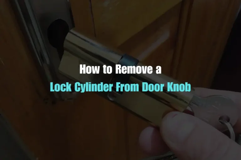
Lock cylinders are essential components in many automated systems, providing safety and precision. Whether you need to replace a worn-out cylinder or upgrade your system, knowing how to remove lock cylinder from door knob is crucial. This guide will help you to use simple, easy-to-follow steps to remove a lock cylinder from door knob. What is a Door Lock Cylinder? The cylinder is the part of the lock where you insert your key. It’s the heart of the lock, and without it, the lock won’t work. When you turn the key, the cylinder rotates and moves the locking mechanism inside the door. Why You Need To Remove Lock Cylinder from Door Knob? There are several reasons you might need to remove lock cylinder from door knob: Tools You’ll Need To Remove Lock Cylinder from Door Knob Gather these tools before you start removing lock cylinder from door knob: Step-by-step guide: how to remove lock cylinder from door knob Step 1: Identify Your Lock Type There are different types of door lock cylinders. Identify your specific model to understand its features and locking mechanisms. This will help you follow the correct removal steps. Knowing your lock type helps you understand the steps better. Step 2: Remove the Door Handle or Knob For most locks, you need to remove the handle or knob first. Here’s how: Step 3: Remove the Lock Cylinder After removing the handle or knob, you’ll see the lock cylinder. It’s usually held in place by a retaining screw. Use your screwdriver to remove the screw holding the cylinder in place. Gently pull the cylinder out. If it’s stuck, use needle-nose pliers to wiggle it free. Be careful not to force it too hard to avoid damaging the door. Step 4: Dealing with a Stuck Cylinder Sometimes, the cylinder won’t come out easily. Here are some tips to help: Safty Fast Always prioritize safety when working with locks and doors: Conclusion Removing a door lock cylinder might seem daunting, but with the right tools and instructions, it’s a manageable task. Whether you’re dealing with a lost key or upgrading your home’s security, knowing how to handle your door locks can save time and money. Remember to take your time, stay organized, and prioritize safety.
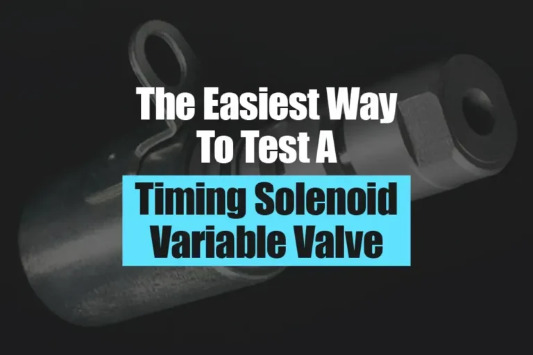
The Easiest Way To Test A Variable Valve Timing Solenoid
This perfect air intake is crucial for good engine performance. It helps the engine run smoother, use less fuel, and even have more power when you need it. So, the VVT is like a tiny air traffic controller for the engine, making sure it gets the right amount of air for optimal performance. What is a Variable Valve Timing Solenoid (VVT)? Your car engine needs air to run, but it needs the right amount at the right time. The variable valve timing solenoid (VVT) is a small but important part that controls this. It works like a switch that opens and closes based on signals from the car’s computer. Imagine the engine has air vents, like the ones in your house. The VVT controls when these vents open and close. By carefully timing when these vents open and shut, the VVT ensures the engine gets the exact amount of air it needs. How Does A Variable Valve Timing Solenoid Work? Signs of a Bad Variable Valve Timing Solenoid (VVT) A VVT solenoid is a small but important part in your car engine. It controls when the engine valves open and close, affecting how the engine runs. Here are some signs that your VVT solenoid might be failing: Check Engine Light: Most modern cars will warn you with a check engine light if they detect a problem with the VVT system. This light is like a dashboard warning sign, telling you there’s an issue. Rough Idling: If your engine feels shaky or vibrates more than usual when idling (stopped but engine running), it could be a VVT problem. Poor Gas Mileage: The VVT system helps optimize fuel efficiency. If it’s not working right, your car might use more gas than usual. Decreased Engine Power: A failing VVT solenoid can affect how much power your engine produces. You might notice the car feels sluggish or struggles to accelerate. How To Install A Variable Valve Timing Solenoid? This is a basic guide to test your VVT solenoid. It’s recommended to consult a mechanic if you’re unsure about any steps. Tools The purge valve solenoid is a part that controls fuel vapors in your car. If it’s broken, you might need to replace it. Here’s a general guide, but remember the exact steps might differ depending on your car model:
How to Fix a Stuck Solenoid Valve (Simple Guide)
Solenoids are simple parts in machines that open and close. But when they malfunction, they can cause big problems. Here’s the complete guide on how to fix a stuck solenoid valve. It’s often hard to tell why a solenoid isn’t working because they are small and simple. A repair person needs to find the cause of the problem. Common Problems of Stuck Solenoid Valve Problem 1 – Stuck Open or Closed Valve A Solenoid is often stuck when it loses power or cannot channel enough electricity to the coil. Additionally, coil burnout or failure can also cause the valve to be stuck open or closed. Sometimes, when the circuitry faces a power interruption, the valve can get stuck and stay that way when you restore the power. Problem 2 – Valve Opens Without Prompts This is a complex issue and depends on other parts of the system. For example, electrical surges in the circuit, or hydraulic pressure brought on against the valve can cause the valve to open randomly without prompting. A technician needs to run a series of tests to find out what’s causing the valve to open, and then fix it accordingly. Problem 3 – Valve Won’t Close When a valve doesn’t close properly, start from closely scrutinizing the solenoid itself. Keep an eye out for any debris or some kind of foreign object stuck inside the stem, causing the valve to function faultily. In case there isn’t any debris, look for a possible power disruption issue. Make sure the solenoid circuit has adequate power, and in case it lacks power, try restoring and resetting the solenoid. If still the problem persists, check the valve’s alignment. Misalignment often prevents the valve from closing properly. Make sure you inspect the stem and seat for any visible signs of damage -indicating a forced opening. By following these steps, you should be able to identify and fix the problem with your solenoid valve. If you’re unsure or the problem persists, consult a qualified technician for help. How to Fix a Stuck Solenoid Valve (Step-By-Step Guide) Having trouble with your sprinklers? It might be a faulty solenoid valve. Here’s a simple guide on how to fix a stuck solenoid valve. If you’re not comfortable with any of these steps, call a qualified technician. Electrical Issues Check the Fuse: Locate the fuse box on your irrigation controller. Consult the manual to identify the correct fuse for the solenoid valves. Replace the Fuse: If the fuse is blown, replace it with a fuse of the same amperage rating. Never use a higher amperage fuse. Blown fuses can happen if the valves were wired incorrectly in the past. Wiring Check Turn Off Power: Before touching any wires, make sure the power to your irrigation controller is completely off. Match the Wires: Each solenoid valve should have two wires connected to the coil. Follow these wires back to the irrigation controller. Common Terminal: One wire should be connected to the “common” terminal on the controller. This terminal is usually labeled clearly in the manual or on the controller itself. Station Terminal: The other wire should be connected to the specific “station” terminal on the controller that corresponds to the valve you’re checking. For example, if the valve controls Zone 3, the wire should be connected to the “Station 3” terminal. Secure Connections: Make sure all the wire connections are tight and secure. Loose or corroded connections can also cause problems. Valve Issues Flow Control Stem. Locate the flow control stem on the solenoid valve. It’s usually a knob or screw-like adjustment on the valve body. Open the Stem. Turn the flow control stem fully counter-clockwise to open it completely. This will allow for maximum water flow through the valve. Wrong Direction? Flow Arrow. Double-check the direction of the valve. There should be an arrow clearly marked on the valve body indicating the direction of water flow. Match the Arrow. Make sure the arrow points in the same direction as the water flow in your system. If the valve is installed backwards, it won’t open properly. Manual Switch Check Locate the Switch: Some solenoid valves have a small manual switch near the coil. This switch allows you to open the valve manually for testing or flushing purposes. Switch Position. In most cases, the manual switch should be in the “OFF” position. If the switch is in the “ON” position, the valve will stay open even when the controller isn’t sending a signal, allowing water to flow through it even if other valves are not activated. Solenoid Coil Issues Turn Off Power. Before working on the coil, make sure the power to your irrigation controller is completely off. Unscrew the Coil. Carefully unscrew the coil from the valve body. Check the O-ring. Look for a small rubber ring (o-ring) where the coil meets the valve body. This o-ring creates a watertight seal. Replace the O-ring. If the o-ring is missing, damaged, or cracked, replace it with a new one of the same size. Stuck Plunger Unscrew the Coil (see Missing O-Ring above). Follow the steps above to remove the coil. Locate the Plunger. Inside the coil, you should see a small metal rod called a plunger. Test the Plunger. The plunger should move freely up and down when you press it gently with your finger. If it’s stuck, it won’t allow the valve to open properly. Clean the Plunger. If the plunger is stuck, carefully remove it and clean it with clean water. Do not use any lubricant, as this can attract dirt and cause further problems. Reassemble Carefully. Once cleaned, carefully reinsert the plunger back into the coil and screw the coil back onto the valve body. Burned Out Coil Swap the Coil (Optional): If none of the above solutions work, the coil itself might be damaged or burned out. You can try swapping the coil with a known working coil from another valve to test. Be very careful when swapping coils, as you’ll be working with electrical wires. If you’re not comfortable doing this step, call a technician. General Maintenance Clean the Valve. Dirt or debris can build
How To Clean A Variable Valve Timing Solenoid?

Today, most cars that run on gas come with a special feature that allows the valves’ timings to be tweaked according to the RPM, engine load, road conditions and other factors. The most commonly found systems use VVT solenoids or Variable Valve Timing Solenoids. To clean it, locate the solenoid, disconnect it from the engine, remove dirt and grime with a cleaner and cloth, check for damage, and then reconnect the engine safely before testing its operation. In this article, we will share simple steps on how to clean a VVT or variable valve timing solenoid. What is a VVT Solenoid? A Variable Valve Timing (VVT) Solenoid is a crucial component in modern car engines that allows the efficient control of the engine’s valve opening and closing times. This timing adjustment optimizes engine performance, fuel efficiency, and emissions. Essentially, the VVT solenoid helps the engine adapt to different driving conditions by adjusting the valves’ opening and closing times. Why You Should Clean Variable Valve Timing Solenoid? The variable valve timing solenoid is like a traffic controller for construction machinery engines. It helps adjust when valves open and close to make the engine work better and use fuel efficiently. 1. Understanding the VVT Solenoid: Think of the variable valve timing solenoid valve as a traffic controller for construction machinery engines. It adjusts when valves open and close to make the engine work better and use fuel efficiently. 2. Importance of Cleaning: Over time, dirt and gunk can build up on the solenoid, causing problems like slow or incorrect actions. Regular cleaning is crucial to maintain optimal performance. 3. Effect of Dirt Build-up: When the solenoid gets clogged up, it’s like having a door that won’t shut properly, leading to wasted fuel. Cleaning it helps the engine work smoothly and use less fuel, which is beneficial for the environment. 4. Preventing Engine Damage: If the solenoid remains dirty or stuck, it can disrupt the engine’s operation and even cause damage. Regular cleaning prevents such issues and ensures the engine runs well. 5. Lifespan: Regular cleaning prevents more dirt from piling up and reduces the risk of the solenoid breaking due to dirt accumulation. This prolongs the solenoid’s lifespan, saving you money on repairs in the long run. Why Variable Valve Timing Solenoid Gets Clogged? The variable valve timing solenoid gets clogged due to dust, oil, and other dirty stuff that build up over the years. This buildup takes place because the solenoid is inside the engine where it can collect all kinds of gunk from the oil, air, and exhaust. If the engine gets really warm or runs for a long time, it may worsen this buildup. Hence, it’s vital to clean it regularly to hold the whole thing operating smoothly. 5 Simple Steps To Clean Variable Valve Timing Solenoid Cleaning your car engine’s Variable Valve Timing (VVT) solenoid in regular intervals to ensure your car’s engine works smoothly. Here’s how you can do it: Step 1: Getting Ready Step 2: Removing The Valve Step 3: Cleaning The Valve Step 4: Putting Back The Valve Step 5: Testing Signs Your Variable Valve Timing Solenoid Needs Cleaning When you notice these signs, it’s essential to address them promptly by cleaning your VVT valve. Simple maintenance tasks can help keep your engine running smoothly and avoid more significant problems down the road.